INMOS TN70 - Connecting 100MBaud T9000 Transputer Links
페이지 정보

본문
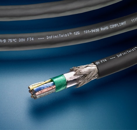 As lengthy as the errors are infrequent (one every a number of thousand years), this is entirely enough. The issue shouldn't be within the attenuation within the cable, but in the losses (and consequent prices) in converting from electricity to gentle at one end and from light to electricity at the other end. Copper wire has a finite resistance: 28AWG wire is one of the smallest cross sections in widespread use and has a resistance of 0.23Ohm/m, 1Ohm in 4.3m. If the characteristic impedance of the cable is 100Ohm, a resistance of 10 ohms just isn't going to have an effect on the signal very much, so this cable ought to definitely be usable at 43m. The problem is that at excessive frequencies, the signal does not move evenly all through the conductor however concentrates at the surface of the conductor - the skin impact. For PCB connections as much as 20cm, the characteristic impedance of the PCB monitor doesn't matter.
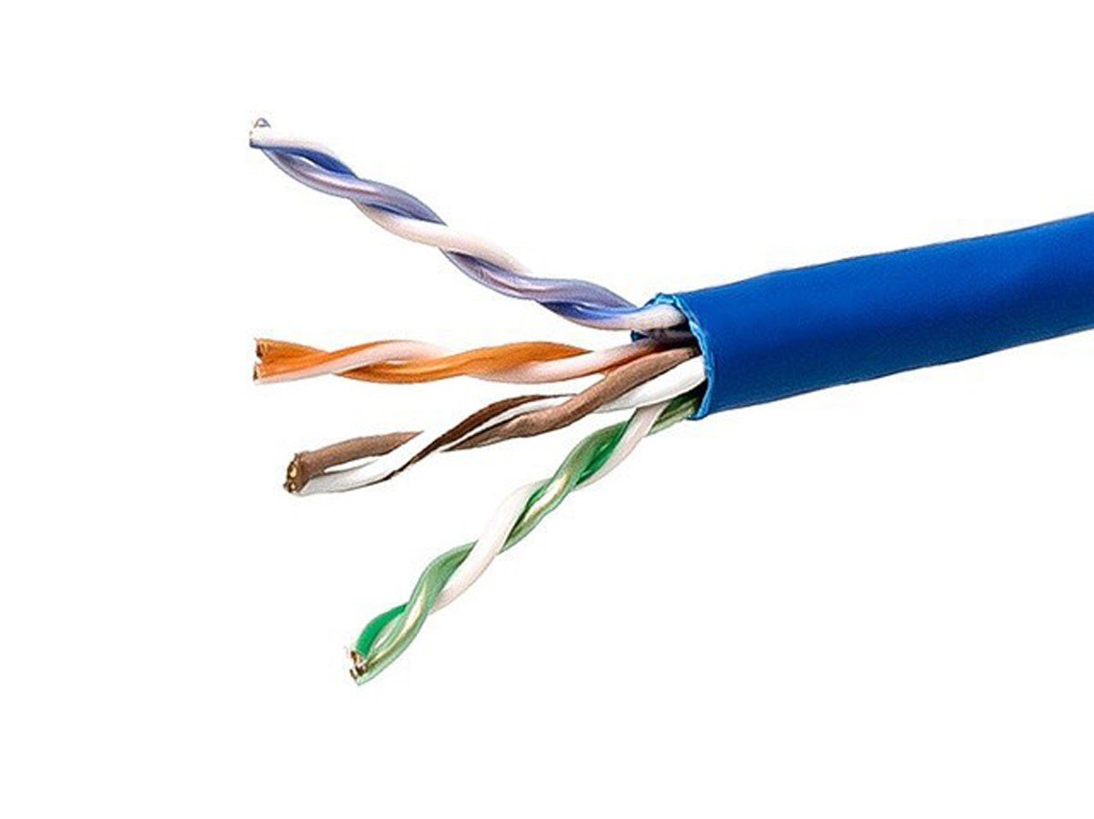 Longer distance connections, with the quantity of amplification required for the optical sign, is such that the connection should be considered as much less dependable than regular brief connections on a PCB. In fact the indications are that it may be potential to realize worst case error rates of the order of 10−20, far better than is achieved by normal communications. DS hyperlinks can be specified, due to this fact, in order that they offer such infrequent errors that the hardware might be thought of reliable, and that the probability of a single bit error is so low that the possibility of an undetected double error is negligible. Components with wavelengths of 820 or 850nm are in lots of respects more appropriate for 100MBaud transputer hyperlinks. Remember, when reading these texts on communications, low voltage twisted pair cable that (while the ideas concerned have to be understood) the distances required and the error rates obtained make transputer links much simpler than telecomms. I hope you guys are clamping your voltages when studying your sensors because minute mV modifications can happen as a consequence of RF and induced flux from the ignition leading to false reads.
Posted by zip on June 17, 1999 at 14:27:19: Just reread my submit and yes your right voltage clamping is used to forestall CMOS from going over their threshold value. Posted by NITRO on June 17, 1999 at 14:45:10: Occasionally a few prototypes are made to be easily accessable and are therefore somewhat "ugly" in configuration. Just a few instance ’scope traces are shown of the waveforms seen with totally different lengths of connection and with different forms of buffering. For example office tools corresponding to terminals, laser printers, disks, and fax machines, each of which might use from two to 4 of the connectors, might use one type of connector; and computer systems, which might use many more connectors, use a unique type. An example LED outputs (infra-purple at 1300nm wave size) 0.25mW of optical power when driven by 100mA of electrical energy. The D and S pair of alerts ought to be approximately the identical length, however a difference in size of 50mm would solely introduce a skew of 250ps, which ought to be completely acceptable.
Any difference might be seen as noise. In magnetic recording, such differentiation occurs naturally, but it surely brings its personal problems; any noise such as crosstalk is coupled by means of the differentiator, and any AC imbalance in common-mode coupling is translated into further noise. Our current proposal for cable connection is for DC coupling with the 41 sequence buffers mentioned earlier, with additional circuitry to improve the (already good) frequent-mode traits of those buffers. For longer connections, as much as 200 or 500m, or for electrical isolation, our current proposal is to make use of low price optical fibre components, with a function designed interface chip. Even with a very broad bandwidth, it is possible to make use of tuning (tweaking?) to compensate for the frequency characteristics of the cable. The dotted line represents the DC threshold of the sign, which means that the sign is not going to be obtained appropriately, even when there is no noise. There are a number of other mounting combinations, which are already undergiong assessments as I communicate.
- 이전글What's Holding Back The Best Sleeper Sofa Industry? 24.12.29
- 다음글The 12 Most Unpleasant Types Of Asbestos Payouts Users You Follow On Twitter 24.12.29
댓글목록
등록된 댓글이 없습니다.